The integrated electrical and mechanical design platform may surprise you with its electronics simulation capabilities for signal integrity and cooling.
Autodesk has sponsored this post.
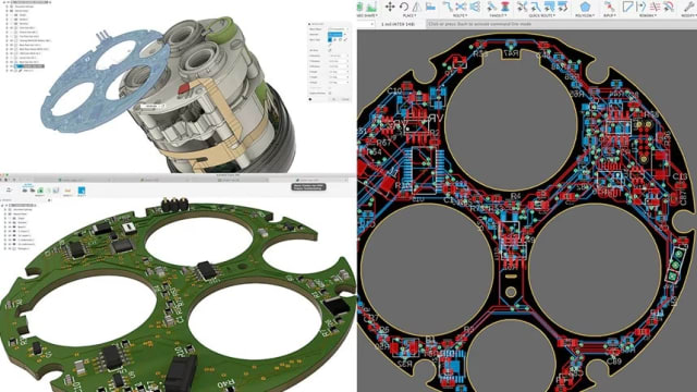
Looking for a comprehensive electronic design tool? Maybe you’ve heard that Autodesk Fusion 360 integrates mechanical and electronic CAD (MCAD and ECAD) into a single package with a smooth workflow, but still aren’t sure if its ECAD functionality runs deep enough for your projects.
You might be surprised. In this article, we’ll dive into Fusion 360’s sophisticated ECAD features—specifically, its electronics simulation capabilities, which include extensions for signal integrity and electronics cooling that can help fast track your product design.
Electronic simulation in Fusion 360
Engineers using Fusion 360 can add optional simulation packages that, while not as feature-rich as some pricier simulators, cover most designs—especially in the consumer electronics market.
For electronics design, two of the most useful simulation tools are the signal integrity extension and the electronics cooling extension. Jorge Garcia, Autodesk’s community manager for Fusion 360, says that these two simulators cover about 80% of all designs, providing insight that catches issues before going into production. This helps to avoid costly PCB re-spins and other redesign complications.
“And for designs that require deeper analyses, the Fusion 360 extensions can serve as an extra set of eyes to catch the ‘trivial’ issues before going to one or both more elaborate tools, which often require a signal integrity or heat transfer specialist,” Garcia told engineering.com.
Signal integrity analysis
Fusion 360’s signal integrity extension, powered by Ansys, allows engineers to locate and correct issues with PCB signals early in the design phase. This helps to facilitate EMC and EMI testing compliance, reduce physical testing and prototyping and, ultimately, get the product to market sooner. The designer can select certain signal paths to determine the resistance, inductance and capacitance of the traces. The extension also analyzes how impedances change along the traces to catch any issues with impedance mismatches.
“Most PCBs have a few critical traces that may be of interest, such as traces with critical impedance requirements. This tool allows the designer to specify what they’re interested in, so they can determine whether each trace has the impedance required for maximum power transfer, along with other signal integrity benefits that come with matching impedance,” said Edwin Robledo, Autodesk’s technical marketing manager for Fusion 360.
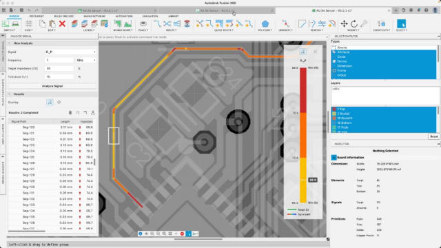
High-frequency circuits present their own set of complications due to stray inductance and capacitance, so the signal integrity extension helps to identify problems with signal delays, trace length, impedance and coupling. It can analyze the product’s high-speed, RF and wireless capabilities to meet your design specs and assure compliance with industry standards and rules.
Robledo says that the user-friendly tool can be easily configured to select signals of interest with a few mouse clicks, and it provides a color-coded output that gives the designer visual clues about the circuit’s operation. For example, green means everything works as intended, red means there is a critical failure on that trace, and colors in between indicate degrees of compliance with specifications.
This low-cost simulator covers the majority of consumer electronic products, but it doesn’t address everything. For example, it doesn’t deal with cross coupling (crosstalk, capacitive and inductive coupling), although Robledo said its implementation is being considered. It’s also not suited for power network design and power distribution systems, or analyzing how currents move through a ground plane.
There is no transient simulation, either. Those niche applications may require a more expensive simulator, so Fusion 360 allows you to export a study from the simulation workspace into Ansys.
Thermal analysis with the electronics cooling extension
Fusion 360’s electronics cooling extension allows engineers to perform a thermal analysis and assess heat dissipation of one or more components, as well as the entire product’s thermal performance. The extension takes into account the component specifications, nearby components, all of the materials in the enclosure, and the case aerodynamics. For systems that have a cooling fan, the engineer can add the fan specs as another factor to consider.
Components and their specs are automatically imported from Fusion 360’s design files. On parts that are likely to dissipate a lot of heat, engineers can manually assign a particular material with a specified heat load. When they specify a component material, the simulator knows all of its heat dissipation properties. The engineer can select which components to analyze and optionally add critical temperatures to each. The analysis will show a color-coded diagram of the circuit. If you specify a critical temperature, it gives a pass/fail result. If critical temperatures are not specified, then it simply gives a temperature gradient.
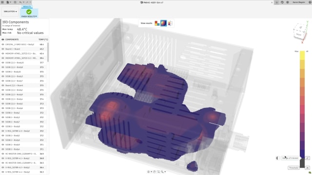
Fusion 360’s electronics cooling extension also displays heat propagation, so if you have a really hot component, you’ll see how the heat spreads to nearby components. This way, you can avoid placing temperature-sensitive components near any high power dissipation parts.
“By visualizing the internal and external temperatures of the product, and engineer can also determine whether the heat will cause discomfort for the user,” Kristin Kilroy, product marketing manager for Fusion 360, told engineering.com. “These insights help to prevent expensive redesigns.”
Like the signal integrity extension, the electronics cooling extension covers the majority of all consumer electronic products, but it’s not a full-blown computational fluid dynamics (CFD) tool. It does not, for example, analyze systems with liquid cooling.
Simulation-driven design in Fusion 360
Fusion 360’s signal integrity extension and electronics cooling extension cover the majority of situations, but neither are the complete analysis tools. So, what is the value of these two extensions in more complicated systems where pricier simulation tools would be employed?
Sometimes the electronics engineer doing the design is not an expert in heat transfer or currents moving through a ground plane. That’s when they call in the specialists who can use the more elaborate simulation packages to analyze the system. But even in a case like that, the designer can perform a preliminary simulation as an extra check before sending it to the specialist. If the expert doesn’t need to deal with problems that could have been solved earlier, they can more quickly apply their expertise and accelerate the iterative design process.
This is all part of Fusion 360’s real power, which is its integration of MCAD, ECAD and simulation tools into one logical workflow. When moving from design to simulation, engineers don’t need to change environments or import/export files—they simply switch datasets.
For example, once you’ve performed a signal integrity analysis and have a functional PCB, you can then add the enclosure, vents, fan and mechanical components, and run a thermal analysis of the entire assembly, all from a single environment. One can even set up multiple simulation models without altering the original design in order to evaluate “what if” scenarios. This integration of MCAD and ECAD allows engineers to simulate the product’s electrical and mechanical performance, and even its manufacturability, all without switching tools.
To learn more about Fusion 360 and the benefits of an integrated ECAD and MCAD platform, visit Autodesk.com.
